(!)Due to Microsoft's end of support for Internet Explorer 11 on 15/06/2022, this site does not support the recommended environment.
68.800 Stock items for Same Day Shipping
68.800 Item Stok untuk Pengiriman di Hari yang Sama
Search by Category / Brand
Pencarian dengan
Kategori / Merek
Search by Category Pencarian dengan Kategori
- Automation Components
A wide variety of standard and configurable components for factory automation engineers in industries such as automotive, semiconductor, packaging, medical and many more.
- Linear Motion
- Rotary Motion
- Connecting Parts
- Rotary Power Transmission
- Motors
- Conveyors & Material Handling
- Locating, Positioning, Jigs & Fixtures
- Inspection
- Sensors, Switches
- Pneumatics, Hydraulics
- Vacuum Components
- Hydraulic Equipment
- Discharging / Painting Devices
- Pipe, Tubes, Hoses & Fittings
- Modules, Units
- Heaters, Temperature Control
- Framing & Support
- Casters, Leveling Mounts, Posts
- Doors, Cabinet Hardware
- Springs, Shock Absorbers
- Adjusting, Fastening, Magnets
- Antivibration, Soundproofing Materials, Safety Products
- Fasteners
A good selection of accessories such as screws, bolts, washers and nuts that you may need for your daily engineering usage.
- Materials
Browse industrial materials ranging from heat insulating plates, sponges, to metal and plastic materials in different sizes to meet your various applications.
- Wiring Components
A wide variety of wiring parts for connecting and protecting control and PC parts including Connectors, Cables, Electric Wires, Crimping Terminals and more.
- LAN Cables / Industrial Network Cables
- Cables by Application
- Cables with Connectors
- RS232 / Personal Computers / AV Cables
- Wires/Cables
- Connectors (General Purpose)
- Crimp Terminals
- Zip Ties
- Cable Glands
- Cable Bushings/Clips/Stickers
- Screws/Spacers
- Cable Accessories
- Tubes
- Protection Tubes
- Ducts/Wiremolds
- General Purpose Tools
- Dedicated Tools
- Soldering Supplies
- Electrical & Controls
A wide variety of controls and PC parts for electrical engineers including Controls, Powers, PC parts and more.
- Cutting Tools
A wide variety of cutting tools for many uses and work materials including End Mills, Drills, Cutters, Reamers, Turning Tools and more.
- Carbide End Mills
- HSS End Mills
- Milling Cutter Inserts/Holders
- Customized Straight Blade End Mills
- Dedicated Cutters
- Turning Tools
- Drill Bits
- Screw-Hole-Related Tools
- Reamers
- Chamfering / Centering Tools
- Fixtures Related to Cutting Tools
- Step Drills
- Hole Saws
- Clean Key Cutters
- Core Drills (Tip Tools)
- Magnetic Drilling Machine Cutters
- Drill Bits for Electric Drilling Machines
- Woodworking Drill Cutters
- Drills for Concrete
- Processing Tools
A wide variety of tools and supplies used in processing including Machine Tools, Measurement Tools, Grinding and Polishing Supplies and more.
- Material Handling & Storage
A wide variety of goods used in shipment, material handling and warehouse including Tape supplies, Stretch film, Truck, Shelf, Crane and more.
- Tape Supplies
- Cushioning Materials
- Stretch Films
- Cardboard
- Plastic Bags
- PP Bands
- Magic Tapes / Tying Belts
- Rubber Bands
- Strings/Ropes
- Cable Ties
- Tags
- Labelers
- Unpacking Cutters
- Packing Support Equipment
- Cloth Sheets for Packing
- Conveyance/Dolly Carts
- Tool Wagons
- Tool Cabinets / Container Racks
- Lifters / Hand Pallets
- Container Pallets
- Storage Supplies
- Shelves/Racks
- Work Benches
- Suspended Clamps/Suspended Belts
- Jack Winches
- Chain Block Cranes
- Bottles/Containers
- Bicycle Storage Area
- Safety & General Supplies
A large variety of goods for every kind of factories and offices including Protection items, Cleaning supplies, sanitations, office supplies and more.
- Lab & Clean Room Supplies
A large variety of items used in R&D and Clean Room including research Equipment, Laboratory Essentials, Analysis Supplies, Clean Environment-Related Equipment and more.
- Press Die Components
Choose from thousands of standard stamping die components including Punch & Die, Gas Springs, Guide Components, Coil Springs and many more.
- Plastic Mold Components
Browse our wide variety of mold components including Ejector Pins, Sleeves, Leader Components, Sprue Bushings and many more.
- Ejector Pins
- Sleeves, Center Pins
- Core Pins
- Sprue bushings, Gates, and other components
- Date Mark Inserts, Recycle Mark Inserts, Pins with Gas Vent
- Undercut, Plates
- Leader Components, Components for Ejector Space
- Mold Opening Controllers
- Cooling or Heating Components
- Accessories, Others
- Components of Large Mold, Die Casting
- Injection Molding Components
Browse our injection molding components including Heating Items, Couplers, Hoses and more.
- Injection Molding Machine Products
- Accessories of Equipment
- Auxiliary Equipment
- Air Nippers
- Air Cylinders
- Air Chuck for Runner
- Chuck Board Components
- Frames
- Suction Components
- Parallel Air Chuck
- Special Air Chuck
- Chemical for Injection Molding
- Mold Maintenance
- Heating Items
- Heat Insulation Sheets
- Couplers, Plugs, One-touch Joints
- Tubes, Hoses, Peripheral Components
- Komponen Mekanis
- Linear Motion
- Rotary Motion
- Connecting Parts
- Rotary Power Transmission
- Motors
- Conveyors & Material Handling
- Locating, Positioning, Jigs & Fixtures
- Inspection
- Sensors, Switches
- Pneumatics, Hydraulics
- Vacuum Components
- Hydraulic Equipment
- Discharging / Painting Devices
- Pipe, Tubes, Hoses & Fittings
- Modules, Units
- Heaters, Temperature Control
- Framing & Support
- Casters, Leveling Mounts, Posts
- Doors, Cabinet Hardware
- Springs, Shock Absorbers
- Adjusting, Fastening, Magnets
- Antivibration, Soundproofing Materials, Safety Products
- Sekrup, Baut, Washer, Nut
- Material
- Komponen Kabel
- LAN Cables / Industrial Network Cables
- Cables by Application
- Cables with Connectors
- RS232 / Personal Computers / AV Cables
- Wires/Cables
- Connectors (General Purpose)
- Crimp Terminals
- Zip Ties
- Cable Glands
- Cable Bushings/Clips/Stickers
- Screws/Spacers
- Cable Accessories
- Tubes
- Protection Tubes
- Ducts/Wiremolds
- General Purpose Tools
- Dedicated Tools
- Soldering Supplies
- Elektrikal & Kontrol
- Peralatan Pemotong
- Carbide End Mills
- HSS End Mills
- Milling Cutter Inserts/Holders
- Customized Straight Blade End Mills
- Dedicated Cutters
- Turning Tools
- Drill Bits
- Screw-Hole-Related Tools
- Reamers
- Chamfering / Centering Tools
- Fixtures Related to Cutting Tools
- Step Drills
- Hole Saws
- Clean Key Cutters
- Core Drills (Tip Tools)
- Magnetic Drilling Machine Cutters
- Drill Bits for Electric Drilling Machines
- Woodworking Drill Cutters
- Drills for Concrete
- Peralatan Produksi
- Penanganan Material & Penyimpanan
- Tape Supplies
- Cushioning Materials
- Stretch Films
- Cardboard
- Plastic Bags
- PP Bands
- Magic Tapes / Tying Belts
- Rubber Bands
- Strings/Ropes
- Cable Ties
- Tags
- Labelers
- Unpacking Cutters
- Packing Support Equipment
- Cloth Sheets for Packing
- Conveyance/Dolly Carts
- Tool Wagons
- Tool Cabinets / Container Racks
- Lifters / Hand Pallets
- Container Pallets
- Storage Supplies
- Shelves/Racks
- Work Benches
- Suspended Clamps/Suspended Belts
- Jack Winches
- Chain Block Cranes
- Bottles/Containers
- Bicycle Storage Area
- Perlengkapan Keamanan & Umum
- Perlengkapan Sanitasi & Lab
- Komponen Press Die
- Komponen Plastik Mold
- Ejector Pins
- Sleeves, Center Pins
- Core Pins
- Sprue bushings, Gates, and other components
- Date Mark Inserts, Recycle Mark Inserts, Pins with Gas Vent
- Undercut, Plates
- Leader Components, Components for Ejector Space
- Mold Opening Controllers
- Cooling or Heating Components
- Accessories, Others
- Components of Large Mold, Die Casting
- Komponen Injeksi Moulding
- Injection Molding Machine Products
- Accessories of Equipment
- Auxiliary Equipment
- Air Nippers
- Air Cylinders
- Air Chuck for Runner
- Chuck Board Components
- Frames
- Suction Components
- Parallel Air Chuck
- Special Air Chuck
- Chemical for Injection Molding
- Mold Maintenance
- Heating Items
- Heat Insulation Sheets
- Couplers, Plugs, One-touch Joints
- Tubes, Hoses, Peripheral Components
Search by Brand Pencarian dengan Merek
This translation is a Google translation Terjemahan ini adalah terjemahan Google
- Pemberitahuan Jadwal Pemeliharaan : Situs ini akan tidak tersedia dikarenaka jadwal pemeliharaan mulai dari 8:00 15/12/2024 sampai dengan 5:00 pada tanggal 16/12/2024. Kami mohon maaf atas ketidaknyamanan yang terjadi.
Scheduled Maintenance Notice: This site will be unavailable due to scheduled maintenance from 8:00 15/12/2024 to 5:00 (WIB) 16/12/2024. We apologize for the inconvenience. - Penghentian penjualan kategori produk pneumatik Seri Ekonomi (E-series). Info Detail
Notice of End of Sales for Economy Series Pneumatic Equipment Category. More information.
CKQGD/CKQPD/CLKQGD/CLKQPD Series Pin Clamp Cylinder (CLKQPDB50TF-175RCH-P79WSE)
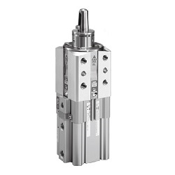
Adjustable height for clamping a workpiece.
[Features]
· Possible to mount on 4 surfaces, and 2 auto switches on the same surface, for improved flexibility of system design.
· For improved workability, direct mounting is possible, no mounting hardware required.
· 55 types of guide pins.
· Fine adjustment of the clamping height is possible by selecting the type with shims.
· Optional locking mechanism can be selected.
· The D-P4DW auto switch is also mountable.
· 2 switches can be mounted on the same surface.
(i)Caution
- See the catalog for specification details.
- Product images may be representative images. Refer to the manufacturer's catalog for shape details.
Part Number
Configured Part Number is shown.
CLKQPDB50TF-175RCH-P79WSE
Model Number Notation
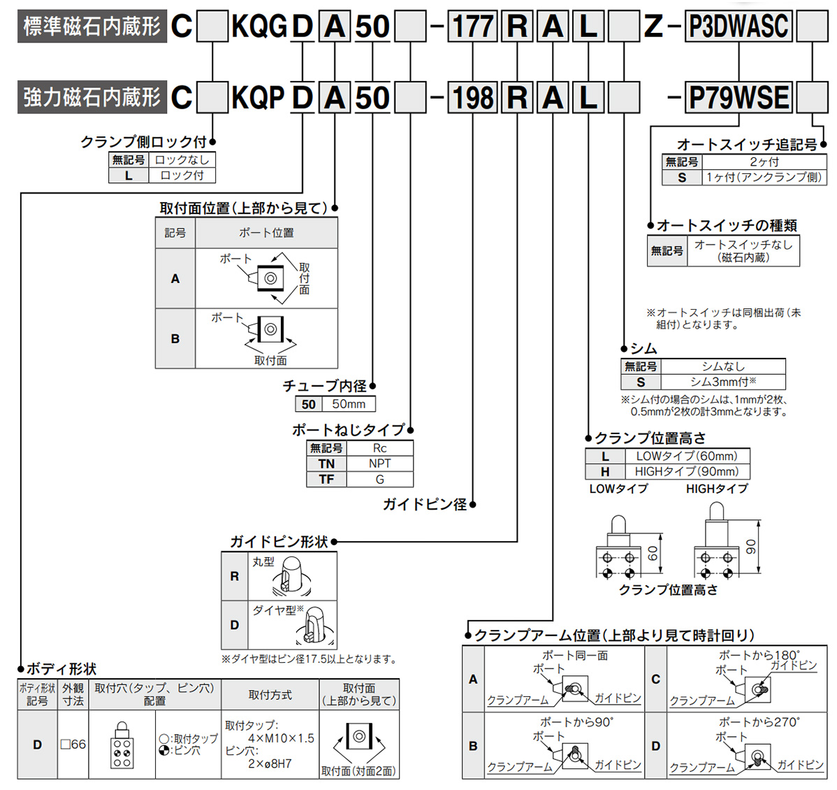
Model Number Notation
CKQGD/CKQPD/CLKQGD/CLKQPD Series Pin Clamp Cylinder Specifications
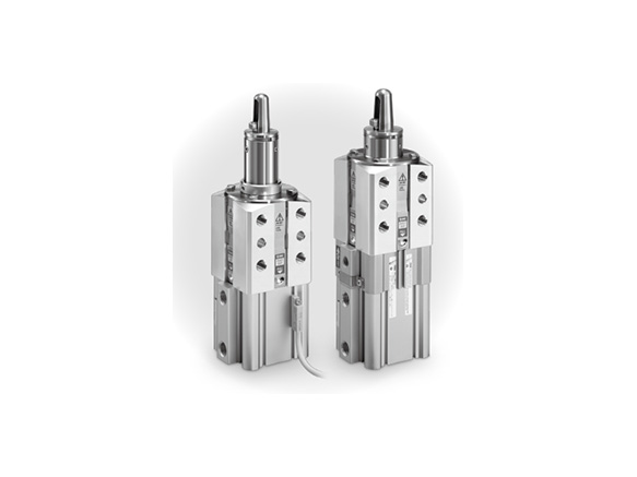
Pin Clamp Cylinder external appearance
*The images for this series are representative images.
![D series external appearance (mounting tap: 4 × M10 × 1.5 / Pin hole: 2 × ø8 [diameter 8 mm] H7)](http://id.misumi-ec.com/linked/vitem/mech/SMC1/221300251725/img/221300251725_jh_w02.jpg)
D series external appearance (mounting tap: 4 × M10 × 1.5 / Pin hole: 2 × ø8 [diameter 8 mm] H7)
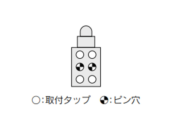
Taps parallel: mounting hole (tap, pin hole) arrangement
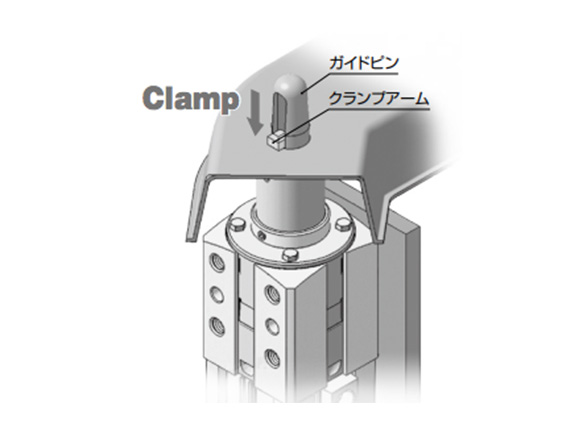
Positioning and clamping can be done at the same time
Basic Specifications
| Action | Double acting | |||
|---|---|---|---|---|
| Bore size | 50 mm | |||
| Fluid | Air | |||
| Min. operating pressure | CKQ□: 0.1 MPa | CLKQ□ (with lock): 0.15 MPa* | ||
| Max. operating pressure | Guide pin diameter | ø12.5 to 13.0 (guide pin diameter 12.5 to 13.0 mm) | 0.7 MPa | |
| ø14.5 to 30.0 (guide pin diameter 14.5 to 30.0 mm) | 1.0 MPa | |||
| Proof pressure | Guide pin diameter | ø12.5 to 13.0 (guide pin diameter 12.5 to 13.0 mm) | 1.0 MPa | |
| ø14.5 to 30.0 (guide pin diameter 14.5 to 30.0 mm) | 1.5 MPa | |||
| Ambient and fluid temperature | -10°C to 60℃ (no freezing) | |||
| Cushion | None | |||
| Lubrication | Non-lube | |||
| Piston speed (clamp speed) | 50 to 150 mm/sec | |||
| Port size (cylinder port) | 1/4 (Rc, NPT, G) | |||
*Minimum operating pressure is 0.2 MPa when cylinder part and locking part use the same piping.
Lock Specifications
| Locking action | Spring locking (exhaust locking) |
|---|---|
| Unlocking pressure | 0.2 MPa or more |
| Locking pressure | 0.05 MPa or less |
| Locking direction | Lock at extended direction (clamp holding) |
| Port size (lock release port) | 1/8 (Rc, NPT, G) |
| Holding force (maximum static load) | 982 N |
Clamping Force
(Unit: N)
| Model | Guide pin diameter | Operating pressure MPa | ||||||||
|---|---|---|---|---|---|---|---|---|---|---|
| 0.2 | 0.3 | 0.4 | 0.5 | 0.6 | 0.7 | 0.8 | 0.9 | 1.0 | ||
| CKQG CKQP | ø12.5 to 13.0 (guide pin diameter 12.5 to 13.0 mm) | 164.9 | 329.8 | 494.7 | 659.6 | 824.5 | 989.4 | - | - | - |
| ø14.5 to 30.0 (guide pin diameter 14.5 to 30.0 mm) | 164.9 | 329.8 | 494.7 | 659.6 | 824.5 | 989.4 | 1,154.3 | 1,319.2 | 1,484.1 | |
| CLKQG CLKQP | ø12.5 to 13.0 (guide pin diameter 12.5 to 13.0 mm) | 82.4 | 247.3 | 412.2 | 577.1 | 742.0 | 906.9 | - | - | - |
| ø14.5 to 30.0 (guide pin diameter 14.5 to 30.0 mm) | 82.4 | 247.3 | 412.2 | 577.1 | 742.0 | 906.9 | 1,071.8*1 | 1,236.7*1 | 1,401.6*1 | |
*1 The lock holding force of the CLKQ□ is 982 N. Design the circuit such that the lock holding force is taken into consideration when the operating pressure exceeds 0.75 MPa. The operating pressure should not be greater than the lock holding force as it may cause wearing out and/or damage of the locking part and shorten the lock life and may lead to possible failure if applied with a load larger than the lock holding force.
*2 It takes approximately 0.3 seconds for the cylinder to operate to generate clamping force from an unclamping state (when no speed controller is installed). Design the circuit taking into consideration the time before the clamping force is generated.
*3 Determine the clamping force according to the strength of the workpiece. It can be damaged if the clamping force is too large.
Weight
(unit: kg)
| Model | C(L)KQGD C(L)KQPD | |||
|---|---|---|---|---|
| Guide pin diameter (mm) | Without lock | With lock | ||
| LOW | HIGH | LOW | HIGH | |
| ø12.5 to 13.0 (guide pin diameter 12.5 to 13.0 mm) | 1.62 | 1.79 | 2.14 | 2.3 |
| ø14.5 to 15.0 (guide pin diameter 14.5 to 15.0 mm) | 1.62 | 1.79 | 2.14 | 2.3 |
| ø15.5 to 16.0 (guide pin diameter 15.5 to 16.0 mm) | 1.63 | 1.79 | 2.14 | 2.31 |
| ø17.5 to 18.0 (guide pin diameter 17.5 to 18.0 mm) | 1.67 | 1.84 | 2.18 | 2.36 |
| ø19.5 to 20.0 (guide pin diameter 19.5 to 20.0 mm) | 1.68 | 1.85 | 2.19 | 2.37 |
| ø24.5 to 25.0 (guide pin diameter 24.5 to 25.0 mm) | 1.74 | 1.94 | 2.25 | 2.46 |
| ø29.5 to 30.0 (guide pin diameter 29.5 to 30.0 mm) | 1.78 | 1.98 | 2.29 | 2.5 |
CKQGDA50/CKQPDA50 external dimensional drawing
- *Refer to the manufacturer's catalog for the positional relationship of the mounting surface and port.
- *The figures below show the CKQGDA50-□RAHZ.
(Unit: mm)
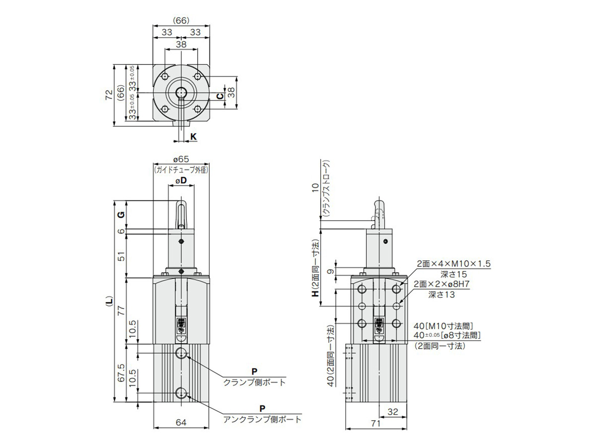
CKQGDA50-□RAHZ dimensional drawing
(Unit: mm)
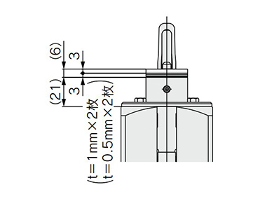
LOW type with shims dimensional drawing
(Unit: mm)
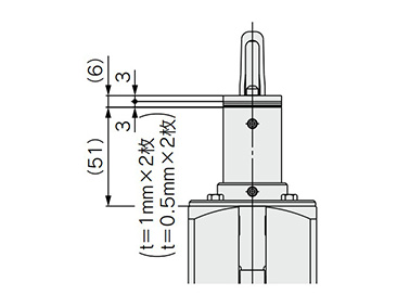
HIGH type with shims dimensional drawing
(Unit: mm)
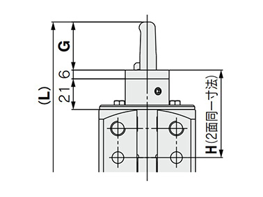
LOW type dimensional drawing
(Unit: mm)
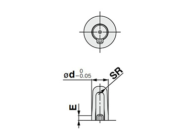
Round type guide pin shape dimensional drawing
(Unit: mm)
![Diamond type guide pin shape dimensional drawing (ø17.5 [guide pin diameter 17.5 mm] or more)](http://id.misumi-ec.com/linked/vitem/mech/SMC1/221300251725/img/221300251725_jh_w10.jpg)
Diamond type guide pin shape dimensional drawing (ø17.5 [guide pin diameter 17.5 mm] or more)
(Unit: mm)
| Hole diameter of workpiece | C | øD | ød | E | G | H | K | L | SR | W | øZ | ||
|---|---|---|---|---|---|---|---|---|---|---|---|---|---|
| LOW Type | HIGH Type | LOW Type | HIGH Type | ||||||||||
| ø13 (hole diameter of workpiece 13 mm) | 9 | ø30 (diameter 30 mm) | ø12.5 (diameter 12.5 mm) | ≈ 10 | 33 | Without shims 60 ±0.05 | Without shims 90 ±0.05 | 6 | 204.5 | 234.5 | 4 | - | ø36 (diameter 36 mm) |
| ø12.7 (diameter 12.7 mm) | ≒9 | ||||||||||||
| ø12.8 (diameter 12.8 mm) | ≒8 | ||||||||||||
| With shims 60 | With shims 90 | ||||||||||||
| ø12.9 (diameter 12.9 mm) | ≒8 | ||||||||||||
| ø13.0 (diameter 13.0 mm) | ≒7 | ||||||||||||
| ø15 (hole diameter of workpiece 15 mm) | 11 | ø30 (diameter 30 mm) | ø14.5 (diameter 14.5 mm) | ≒9 | 34 | Without shims 60 ±0.05 | Without shims 90 ±0.05 | 7 | 205.5 | 235.5 | 5 | - | ø36 (diameter 36 mm) |
| ø14.7 (diameter 14.7 mm) | ≒8 | ||||||||||||
| ø14.8 (diameter 14.8 mm) | ≒8 | ||||||||||||
| With shims 60 | With shims 90 | ||||||||||||
| ø14.9 (diameter 14.9 mm) | ≒7 | ||||||||||||
| ø15.0 (diameter 15.0 mm) | ≒7 | ||||||||||||
| ø16 (hole diameter of workpiece 16 mm) | 11 | ø30 (diameter 30 mm) | ø15.5 (diameter 15.5 mm) | ≈ 10 | 34 | Without shims 60 ±0.05 | Without shims 90 ±0.05 | 7 | 205.5 | 235.5 | 5.5 | - | ø36 (diameter 36 mm) |
| ø15.7 (diameter 15.7 mm) | ≒9 | ||||||||||||
| ø15.8 (diameter 15.8 mm) | ≒8 | ||||||||||||
| With shims 60 | With shims 90 | ||||||||||||
| ø15.9 (diameter 15.9 mm) | ≒8 | ||||||||||||
| ø16.0 (diameter 16.0 mm) | ≒7 | ||||||||||||
| ø18 (hole diameter of workpiece 18 mm) | 12 | ø35 (diameter 35 mm) | ø17.5 (diameter 17.5 mm) | ≈ 10 | 37 | Without shims 60 ±0.05 | Without shims 90 ±0.05 | 7 | 208.5 | 238.5 | 6 | 6 | ø40 (diameter 40 mm) |
| ø17.7 (diameter 17.7 mm) | ≒9 | ||||||||||||
| ø17.8 (diameter 17.8 mm) | ≒8 | ||||||||||||
| With shims 60 | With shims 90 | ||||||||||||
| ø17.9 (diameter 17.9 mm) | ≒8 | ||||||||||||
| ø18.0 (diameter 18.0 mm) | ≒7 | ||||||||||||
| ø20 (hole diameter of workpiece 20 mm) | 13 | ø35 (diameter 35 mm) | ø19.5 (diameter 19.5 mm) | ≈ 10 | 39 | Without shims 60 ±0.05 | Without shims 90 ±0.05 | 8 | 210.5 | 240.5 | 7 | 7 | ø40 (diameter 40 mm) |
| ø19.7 (diameter 19.7 mm) | ≒9 | ||||||||||||
| ø19.8 (diameter 19.8 mm) | ≒8 | ||||||||||||
| With shims 60 | With shims 90 | ||||||||||||
| ø19.9 (diameter 19.9 mm) | ≒8 | ||||||||||||
| ø20.0 (diameter 20.0 mm) | ≒7 | ||||||||||||
| ø25 (hole diameter of workpiece 25 mm) | 16 | ø40 (diameter 40 mm) | ø24.5 (diameter 24.5 mm) | ≈ 10 | 39 | Without shims 60 ±0.05 | Without shims 90 ±0.05 | 8 | 210.5 | 240.5 | 9.5 | 7 | ø47 (diameter 47 mm) |
| ø24.7 (diameter 24.7 mm) | ≒9 | ||||||||||||
| ø24.8 (diameter 24.8 mm) | ≒8 | ||||||||||||
| With shims 60 | With shims 90 | ||||||||||||
| ø24.9 (diameter 24.9 mm) | ≒8 | ||||||||||||
| ø25.0 (diameter 25.0 mm) | ≒7 | ||||||||||||
| ø30 (hole diameter of workpiece 30 mm) | 18 | ø40 (diameter 40 mm) | ø29.5 (diameter 29.5 mm) | ≈ 10 | 39 | Without shims 60 ±0.05 | Without shims 90 ±0.05 | 8 | 210.5 | 240.5 | 11 | 9 | ø47 (diameter 47 mm) |
| ø29.7 (diameter 29.7 mm) | ≒9 | ||||||||||||
| ø29.8 (diameter 29.8 mm) | ≒8 | ||||||||||||
| With shims 60 | With shims 90 | ||||||||||||
| ø29.9 (diameter 29.9 mm) | ≒8 | ||||||||||||
| ø30.0 (diameter 30.0 mm) | ≒7 | ||||||||||||
P: port thread type
- Nil: Rc1/4
- TN: NPT1/4
- TF: G1/4
Precautions
Caution on Design
- *There is a possibility of dangerous sudden action by cylinders if sliding parts of machinery are twisted due to external forces, etc.
In such cases, human injury may occur; e.g. by catching hands or feet in the machinery, or damage to the machinery itself may occur. Therefore, the machine should be adjusted to operate smoothly and designed to avoid such dangers. - *A protective cover is recommended to minimize the risk of personal injury.
If a stationary object and moving parts of a cylinder are in close proximity, personal injury may occur. Design the structure to avoid contact with the human body. - *Securely tighten all stationary parts and connected parts so that they will not become loose.
Especially when a cylinder operates with high frequency or is installed where there is a lot of vibration, ensure that all parts remain secure. - *Design the equipment so that the maximum theoretical force is not applied to the cylinder.
If the cylinder becomes damaged there is a danger of human injury and/or equipment damage. - *Select the mounting base by taking into consideration its rigidity because the cylinder applies a large amount of force.
Otherwise there is a danger of human injury and/or equipment damage. - *Consider the possibility of a decrease in circuit pressure when power is turned off.
If the cylinder is used for a clamping application there is a danger of the workpiece being released since the circuit pressure decreases when the power is turned off. Install safety equipment to prevent human injury and damage to machine and/or equipment. The same consideration should be given for hanging or lift applications to prevent dropping of a workpiece. - *Consider a possible loss of power source.
Measures should be taken to protect against bodily injury and equipment damage in the event that there is a loss of power to equipment controlled by pneumatics, electricity or hydraulics. - *Consider emergency stops.
Design so that human injury and/or damage to machinery and equipment will not be caused when machinery is stopped by a safety device under abnormal conditions, a power outage or a manual emergency stop. - *Consider the action when operation is restarted after an emergency stop or abnormal stop.
Design the machinery so that human injury or equipment damage will not occur upon restart of operation. When the cylinder has to be reset at the starting position, install manual safety equipment. - *Intermediate stop
In the case of the 3-position closed center of a valve, it is difficult to make a piston stop at the required position as accurately and precisely as with hydraulic pressure due to compressibility of air. Furthermore, since valves and cylinders, etc., are not guaranteed for zero air leakage, it may not be possible to hold a stopped position for an extended period of time. Contact the manufacturer if it is necessary to hold a stopped position for an extended period. Do not intermediately stop the CLKQ cylinder during a locking operation because it will shorten the life of the cylinder.
Other precautions
- *Be sure to read the safety precautions and individual product precautions before use.
- *The photos show representative examples of the series. This product's specifications may differ.
- *See the manufacturer's catalog for product information other than the above.
| Part Number |
|---|
| CLKQPDB50TF-175RCH-P79WSE |
| Part Number | Standard Unit Price | Minimum order quantity | Volume Discount | Days to Ship | Cylinder Dia. (Ø) | Max. Pressure (MPa) | Clamping Force (kN) | Auto Switches | Lead Wire Length (m) | The number of the switches | Specifications | Clamp Side Lock | Mounting surface position | Port Screw Type | Guide Pin Diameter | Guide Pin Shape | Clamp Arm Position | Clamp Position Height | Shim | Connector type |
|---|---|---|---|---|---|---|---|---|---|---|---|---|---|---|---|---|---|---|---|---|
- | 1 Piece(s) | Quote | 50 | 1 | 0.577 | P79WSE | 0.3 | 2 pcs. | Built-in strong magnet type | With lock | Same direction as port, 180° from port | G | ø17.5 | Round type | 180° from port | HIGH type (90 mm) | Without shims | - |
Loading...
Basic Information
| Operation Method | Straight Advancing Stroke | Stroke(mm) | 10 | Support Type | Tap |
|---|---|---|---|---|---|
| Rod Tip Shape | Others | Rod Motion | Double Acting Piece Rod | Body Options | No (Standard) |
| Operating Temperature Range(°C) | -10::60 |
Please check the type/dimensions/specifications of the part CLKQPDB50TF-175RCH-P79WSE in the CKQGD/CKQPD/CLKQGD/CLKQPD Series Pin Clamp Cylinder series.
Specification/Dimensions
-
Connector type
- M12-3/4 pin
- M12-1/4 pin
- None
-
type
- CKQGDA50□
- CKQGDB50□
- CKQPDA50□
- CKQPDB50□
- CLKQGDA50□
- CLKQGDB50□
- CLKQPDA50□
- CLKQPDB50□
-
Cylinder Dia.(Ø)
-
Max. Pressure(MPa)
-
Clamping Force(kN)
-
Auto Switches
-
Lead Wire Length(m)
- 0.3
- 0.5
- 3
- 5
- None
-
The number of the switches
-
Specifications
- Built-in standard magnet type
- Built-in strong magnet type
-
Clamp Side Lock
- With lock
- Without lock
-
Mounting surface position
- 90° from port, 270° from port
- Same direction as port, 180° from port
-
Port Screw Type
- G
- NPT
- Rc
-
Guide Pin Diameter
- ø12.5
- ø12.7
- ø12.8
- ø12.9
- ø13
- ø14.5
- ø14.7
- ø14.8
- ø14.9
- ø15
- ø15.5
- ø15.7
- ø15.8
- ø15.9
- ø16
- ø17.5
- ø17.7
- ø17.8
- ø17.9
- ø18
- ø19.5
- ø19.7
- ø19.8
- ø19.9
- ø20
- ø24.5
- ø24.7
- ø24.8
- ø24.9
- ø25
- ø29.5
- ø29.7
- ø29.8
- ø29.9
- ø30
-
Guide Pin Shape
- Diamond type
- Round type
-
Clamp Arm Position
- 90° from port
- 180° from port
- 270° from port
- Same direction as port
-
Clamp Position Height
- LOW type (60 mm)
- HIGH type (90 mm)
-
Shim
- With 3‑mm shims
- Without shims
-
CAD
- 2D
- 3D
Days to Ship
-
- All
- 20 Day(s) or Less
- 21 Day(s) or Less
- 53 Day(s) or Less
Specify Alterations
- The specifications and dimensions of some parts may not be fully covered. For exact details, refer to manufacturer catalogs .
Products like this...
| Part Number |
|---|
| CKQGDA50-125RBLZ-M9BWL |
| CKQGDA50-127RALSZ-M9B |
| CKQGDA50-127RDLZ |
| CLKQPDB50TF-178RBHS-P79WSE |
| CLKQPDB50TF-195RAHS-P74L |
| CLKQPDB50TF-195RAHS-P79WSE |
| Part Number | Standard Unit Price | Minimum order quantity | Volume Discount | Days to Ship | Cylinder Dia. (Ø) | Max. Pressure (MPa) | Clamping Force (kN) | Auto Switches | Lead Wire Length (m) | The number of the switches | Specifications | Clamp Side Lock | Mounting surface position | Port Screw Type | Guide Pin Diameter | Guide Pin Shape | Clamp Arm Position | Clamp Position Height | Shim | Connector type |
|---|---|---|---|---|---|---|---|---|---|---|---|---|---|---|---|---|---|---|---|---|
- | 1 Piece(s) | Quote | - | 0.7 | 0.66 | M9BW | 3 | 2 | Built-in standard magnet type | Without lock | 90° from port, 270° from port | Rc | ø12.5 | Round type | - | LOW type (60 mm) | Without shims | None | ||
- | 1 Piece(s) | Quote | 50 | 0.7 | 0.66 | M9B | 0.5 | 2 pcs. | Built-in standard magnet type | Without lock | 90° from port, 270° from port | Rc | ø12.7 | Round type | Same direction as port | LOW type (60 mm) | With 3‑mm shims | - | ||
- | 1 Piece(s) | Quote | 50 | 0.7 | 0.66 | Without auto switch (built-in magnet) | None | None | Built-in standard magnet type | Without lock | 90° from port, 270° from port | Rc | ø12.7 | Round type | 270° from port | LOW type (60 mm) | Without shims | - | ||
- | 1 Piece(s) | Quote | 50 | 1 | 0.577 | P79WSE | 0.3 | 2 pcs. | Built-in strong magnet type | With lock | Same direction as port, 180° from port | G | ø17.8 | Round type | 90° from port | HIGH type (90 mm) | With 3‑mm shims | - | ||
- | 1 Piece(s) | Quote | 50 | 1 | 0.577 | P74 | 3 | 2 pcs. | Built-in strong magnet type | With lock | Same direction as port, 180° from port | G | ø19.5 | Round type | Same direction as port | HIGH type (90 mm) | With 3‑mm shims | - | ||
- | 1 Piece(s) | Quote | 50 | 1 | 0.577 | P79WSE | 0.3 | 2 pcs. | Built-in strong magnet type | With lock | Same direction as port, 180° from port | G | ø19.5 | Round type | Same direction as port | HIGH type (90 mm) | With 3‑mm shims | - |


How can we improve?Bagaimana Kami bisa meningkatkan Pelayanan?
How can we improve?Bagaimana Kami bisa meningkatkan Pelayanan?
While we are not able to respond directly to comments submitted in this form, the information will be reviewed for future improvement.
Customer Privacy Policy Walaupun Kami tidak dapat langsung menjawab saran yang ditulis di lembar ini, informasinya akan kami review untuk peningkatan pelayanan dikemudian hari
Kebijakan Privacy
Thank you for your cooperation.Terima kasih atas kerjasama anda.
While we are not able to respond directly to comments submitted in this form, the information will be reviewed for future improvement.
Please use the inquiry form.
Customer Privacy Policy Walaupun Kami tidak dapat langsung menjawab saran yang ditulis di lembar ini, informasinya akan kami review untuk peningkatan pelayanan dikemudian hari
Silahkan pergunakan Forms Permintaan.
Kebijakan Privacy