(!)Due to Microsoft's end of support for Internet Explorer 11 on 15/06/2022, this site does not support the recommended environment.
68.800 Stock items for Same Day Shipping
68.800 Item Stok untuk Pengiriman di Hari yang Sama
Search by Category / Brand
Pencarian dengan
Kategori / Merek
Search by Category Pencarian dengan Kategori
- Automation Components
A wide variety of standard and configurable components for factory automation engineers in industries such as automotive, semiconductor, packaging, medical and many more.
- Linear Motion
- Rotary Motion
- Connecting Parts
- Rotary Power Transmission
- Motors
- Conveyors & Material Handling
- Locating, Positioning, Jigs & Fixtures
- Inspection
- Sensors, Switches
- Pneumatics, Hydraulics
- Vacuum Components
- Hydraulic Equipment
- Discharging / Painting Devices
- Pipe, Tubes, Hoses & Fittings
- Modules, Units
- Heaters, Temperature Control
- Framing & Support
- Casters, Leveling Mounts, Posts
- Doors, Cabinet Hardware
- Springs, Shock Absorbers
- Adjusting, Fastening, Magnets
- Antivibration, Soundproofing Materials, Safety Products
- Fasteners
A good selection of accessories such as screws, bolts, washers and nuts that you may need for your daily engineering usage.
- Materials
Browse industrial materials ranging from heat insulating plates, sponges, to metal and plastic materials in different sizes to meet your various applications.
- Wiring Components
A wide variety of wiring parts for connecting and protecting control and PC parts including Connectors, Cables, Electric Wires, Crimping Terminals and more.
- LAN Cables / Industrial Network Cables
- Cables by Application
- Cables with Connectors
- RS232 / Personal Computers / AV Cables
- Wires/Cables
- Connectors (General Purpose)
- Crimp Terminals
- Zip Ties
- Cable Glands
- Cable Bushings/Clips/Stickers
- Screws/Spacers
- Cable Accessories
- Tubes
- Protection Tubes
- Ducts/Wiremolds
- General Purpose Tools
- Dedicated Tools
- Soldering Supplies
- Electrical & Controls
A wide variety of controls and PC parts for electrical engineers including Controls, Powers, PC parts and more.
- Cutting Tools
A wide variety of cutting tools for many uses and work materials including End Mills, Drills, Cutters, Reamers, Turning Tools and more.
- Carbide End Mills
- HSS End Mills
- Milling Cutter Inserts/Holders
- Customized Straight Blade End Mills
- Dedicated Cutters
- Turning Tools
- Drill Bits
- Screw-Hole-Related Tools
- Reamers
- Chamfering / Centering Tools
- Fixtures Related to Cutting Tools
- Step Drills
- Hole Saws
- Clean Key Cutters
- Core Drills (Tip Tools)
- Magnetic Drilling Machine Cutters
- Drill Bits for Electric Drilling Machines
- Woodworking Drill Cutters
- Drills for Concrete
- Processing Tools
A wide variety of tools and supplies used in processing including Machine Tools, Measurement Tools, Grinding and Polishing Supplies and more.
- Material Handling & Storage
A wide variety of goods used in shipment, material handling and warehouse including Tape supplies, Stretch film, Truck, Shelf, Crane and more.
- Tape Supplies
- Cushioning Materials
- Stretch Films
- Cardboard
- Plastic Bags
- PP Bands
- Magic Tapes / Tying Belts
- Rubber Bands
- Strings/Ropes
- Cable Ties
- Tags
- Labelers
- Unpacking Cutters
- Packing Support Equipment
- Cloth Sheets for Packing
- Conveyance/Dolly Carts
- Tool Wagons
- Tool Cabinets / Container Racks
- Lifters / Hand Pallets
- Container Pallets
- Storage Supplies
- Shelves/Racks
- Work Benches
- Suspended Clamps/Suspended Belts
- Jack Winches
- Chain Block Cranes
- Bottles/Containers
- Bicycle Storage Area
- Safety & General Supplies
A large variety of goods for every kind of factories and offices including Protection items, Cleaning supplies, sanitations, office supplies and more.
- Lab & Clean Room Supplies
A large variety of items used in R&D and Clean Room including research Equipment, Laboratory Essentials, Analysis Supplies, Clean Environment-Related Equipment and more.
- Press Die Components
Choose from thousands of standard stamping die components including Punch & Die, Gas Springs, Guide Components, Coil Springs and many more.
- Plastic Mold Components
Browse our wide variety of mold components including Ejector Pins, Sleeves, Leader Components, Sprue Bushings and many more.
- Ejector Pins
- Sleeves, Center Pins
- Core Pins
- Sprue bushings, Gates, and other components
- Date Mark Inserts, Recycle Mark Inserts, Pins with Gas Vent
- Undercut, Plates
- Leader Components, Components for Ejector Space
- Mold Opening Controllers
- Cooling or Heating Components
- Accessories, Others
- Components of Large Mold, Die Casting
- Injection Molding Components
Browse our injection molding components including Heating Items, Couplers, Hoses and more.
- Injection Molding Machine Products
- Accessories of Equipment
- Auxiliary Equipment
- Air Nippers
- Air Cylinders
- Air Chuck for Runner
- Chuck Board Components
- Frames
- Suction Components
- Parallel Air Chuck
- Special Air Chuck
- Chemical for Injection Molding
- Mold Maintenance
- Heating Items
- Heat Insulation Sheets
- Couplers, Plugs, One-touch Joints
- Tubes, Hoses, Peripheral Components
- Komponen Mekanis
- Linear Motion
- Rotary Motion
- Connecting Parts
- Rotary Power Transmission
- Motors
- Conveyors & Material Handling
- Locating, Positioning, Jigs & Fixtures
- Inspection
- Sensors, Switches
- Pneumatics, Hydraulics
- Vacuum Components
- Hydraulic Equipment
- Discharging / Painting Devices
- Pipe, Tubes, Hoses & Fittings
- Modules, Units
- Heaters, Temperature Control
- Framing & Support
- Casters, Leveling Mounts, Posts
- Doors, Cabinet Hardware
- Springs, Shock Absorbers
- Adjusting, Fastening, Magnets
- Antivibration, Soundproofing Materials, Safety Products
- Sekrup, Baut, Washer, Nut
- Material
- Komponen Kabel
- LAN Cables / Industrial Network Cables
- Cables by Application
- Cables with Connectors
- RS232 / Personal Computers / AV Cables
- Wires/Cables
- Connectors (General Purpose)
- Crimp Terminals
- Zip Ties
- Cable Glands
- Cable Bushings/Clips/Stickers
- Screws/Spacers
- Cable Accessories
- Tubes
- Protection Tubes
- Ducts/Wiremolds
- General Purpose Tools
- Dedicated Tools
- Soldering Supplies
- Elektrikal & Kontrol
- Peralatan Pemotong
- Carbide End Mills
- HSS End Mills
- Milling Cutter Inserts/Holders
- Customized Straight Blade End Mills
- Dedicated Cutters
- Turning Tools
- Drill Bits
- Screw-Hole-Related Tools
- Reamers
- Chamfering / Centering Tools
- Fixtures Related to Cutting Tools
- Step Drills
- Hole Saws
- Clean Key Cutters
- Core Drills (Tip Tools)
- Magnetic Drilling Machine Cutters
- Drill Bits for Electric Drilling Machines
- Woodworking Drill Cutters
- Drills for Concrete
- Peralatan Produksi
- Penanganan Material & Penyimpanan
- Tape Supplies
- Cushioning Materials
- Stretch Films
- Cardboard
- Plastic Bags
- PP Bands
- Magic Tapes / Tying Belts
- Rubber Bands
- Strings/Ropes
- Cable Ties
- Tags
- Labelers
- Unpacking Cutters
- Packing Support Equipment
- Cloth Sheets for Packing
- Conveyance/Dolly Carts
- Tool Wagons
- Tool Cabinets / Container Racks
- Lifters / Hand Pallets
- Container Pallets
- Storage Supplies
- Shelves/Racks
- Work Benches
- Suspended Clamps/Suspended Belts
- Jack Winches
- Chain Block Cranes
- Bottles/Containers
- Bicycle Storage Area
- Perlengkapan Keamanan & Umum
- Perlengkapan Sanitasi & Lab
- Komponen Press Die
- Komponen Plastik Mold
- Ejector Pins
- Sleeves, Center Pins
- Core Pins
- Sprue bushings, Gates, and other components
- Date Mark Inserts, Recycle Mark Inserts, Pins with Gas Vent
- Undercut, Plates
- Leader Components, Components for Ejector Space
- Mold Opening Controllers
- Cooling or Heating Components
- Accessories, Others
- Components of Large Mold, Die Casting
- Komponen Injeksi Moulding
- Injection Molding Machine Products
- Accessories of Equipment
- Auxiliary Equipment
- Air Nippers
- Air Cylinders
- Air Chuck for Runner
- Chuck Board Components
- Frames
- Suction Components
- Parallel Air Chuck
- Special Air Chuck
- Chemical for Injection Molding
- Mold Maintenance
- Heating Items
- Heat Insulation Sheets
- Couplers, Plugs, One-touch Joints
- Tubes, Hoses, Peripheral Components
Search by Brand Pencarian dengan Merek


This translation is a Google translation Terjemahan ini adalah terjemahan Google
- Penghentian penjualan kategori produk pneumatik Seri Ekonomi (E-series). Info Detail
Notice of End of Sales for Economy Series Pneumatic Equipment Category. More information.
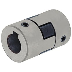
Jaw & Spider Couplings - Set Screw
Click this image to zoom it.
Move the mouse over the image to zoom
"Main body and the spider are of smooth blind fit, making for easy installation, removal and maintenance."
Part Number
Configured Part Number is shown.
Dimensional Drawing
| CPJLW With Keywayed Bore d1, d2 | (No. = 50, 70) | (No. = 75, 90, 95) | |||
 |  | ||||
[!] Operating Temperature: -40°C to 100°C
[ ! ] Recommended Fit Tolerance of Applicable Shaft Diameter: h6 and h7.
[ ! ] The lateral, angular, and axial misalignment values shown are for each occurring individually. When multiple misalignments are occurring simultaneously, the allowable maximum value of each will be reduced to 1/2.
| Material | Surface Treatment | |||
| Hub | Spider | Set Screw | Hub | Set Screw |
| Steel Type Sintered Alloy | NBR | SCM435 | Corrosion Resistant Coating | Black Oxide |
Specification Table
| Part Number | — | Shaft Bore Dia. d1 | — | Shaft Bore Dia. d2 |
| CPF20 | — | 10 | — | 10 |
| CPJLW50 | — | 10 | — | 12 |
| Part Number | d1, d2 Selection (However, d1 ≤ d2) | D | L | ℓ | F | Set Screw | ||||||||||||||||||
| Type | No. | M | Tightening Torque (N⋅m) | |||||||||||||||||||||
| CPJLW | 50 | 10 | 11 | 12 | 14 | 15 | 16 | 27.3 | 43.4 | 15.6 | 8 | M6 | 5 | |||||||||||
| 70 | 11 | 12 | 14 | 15 | 16 | 17 | 18 | 19 | 34.4 | 50.2 | 19 | |||||||||||||
| 75 | 14 | 15 | 16 | 17 | 18 | 19 | 20 | 22 | 44.5 | 54.1 | 20.7 | 7 | ||||||||||||
| 90 | 18 | 19 | 20 | 22 | 24 | 25 | 53.6 | 54.6 | 20.7 | 11.2 | ||||||||||||||
| 95 | 18 | 19 | 20 | 22 | 24 | 25 | 28 | 53.6 | 63.8 | 25.3 | M8 | 10 | ||||||||||||
| Part Number | Allowable Torque (N⋅m) | Allowable Angular Misalignment (°) | Allowable Lateral Misalignment (mm) | Static Torsional Spring Constant (N·m/rad) | Max. Rotational Speed (r/min) | Moment of Inertia (kg⋅m2) | Allowable Axial Misalignment (mm) | Mass (g) | |
| Type | No. | ||||||||
| CPJLW | 50 | 2.1 | 1 | 0.38 | 33.4 | 18000 | 1.6 × 10⁻⁵ | +1.0 0 | 90 |
| 70 | 3.6 | 77.7 | 14000 | 3.3 × 10⁻⁵ | 200 | ||||
| 75 | 8.4 | 241 | 11000 | 1.1 × 10⁻⁴ | +1.1 0 | 360 | |||
| 90 | 9.8 | 317 | 9000 | 2.2 × 10⁻⁴ | 520 | ||||
| 95 | 13.1 | 317 | 9000 | 2.6 × 10⁻⁴ | 570 | ||||
■Features
(CPJLW)
○ A flexible coupling with a simple structure by combination of 2 bodies and 1 spider.
○ Main body and the spider are of smooth blind fit. Easy installation, removal and maintenance.
(Body and spider are detachable.)
Part Number
CAD Data download and 3D preview are not available because the part number has not yet been determined.
- *In order to open the CAD Data download and 3D preview screen, the part number must be fixed.
- Please confirm the part number from "Specification / Dimension"on the left side, and then perform the CAD Data Download / 3D Preview operation.
| Part Number |
|---|
| CPJLW50-[10,11,12,14,15,16]-[10,11,12,14,15,16] |
| CPJLW70-[11,12,14,15,16,17,18,19]-[11,12,14,15,16,17,18,19] |
| CPJLW75-[14,15,16,17,18,19,20,22]-[14,15,16,17,18,19,20,22] |
| CPJLW90-[18,19,20,22,24,25]-[18,19,20,22,24,25] |
| CPJLW95-[18,19,20,22,24,25,28]-[18,19,20,22,24,25,28] |
| Part Number | Standard Unit Price | Minimum order quantity | Volume Discount | Days to Ship | RoHS | O.D. (Ø) | Overall Length (mm) | Allowable Torque Range (N•m) | Max. Rotational Speed Range (r/min) | Allowable Torque (N•m) | Max. Rotational Speed (r/min) | Allowable Axial Misalignment (mm) | Moment of Inertia (kg・m2) | Shaft Bore Dia. 1 (Ø) | Shaft Bore Dia. 2 (Ø) |
|---|---|---|---|---|---|---|---|---|---|---|---|---|---|---|---|
- | 1 Piece(s) | 10 Day(s) or more | 10 | 27.3 | 43.4 | 1.01~3.00 | 10001~78000 | 2.1 | 18000 | +1.0/0 | 1.6 x 10⁻⁵ | 10 ~ 16 | 10 ~ 16 | ||
- | 1 Piece(s) | 10 Day(s) or more | 10 | 34.4 | 50.2 | 3.01~5.00 | 10001~78000 | 3.6 | 14000 | +1.0/0 | 3.3 x 10⁻⁵ | 11 ~ 19 | 11 ~ 19 | ||
- | 1 Piece(s) | 10 Day(s) or more | 10 | 44.5 | 54.1 | 5.01~10.00 | 10001~78000 | 8.4 | 11000 | +1.1/0 | 1.1 x 10⁻⁴ | 14 ~ 22 | 14 ~ 22 | ||
- | 1 Piece(s) | 10 Day(s) or more | 10 | 53.6 | 54.6 | 5.01~10.00 | 4001~10000 | 9.8 | 9000 | +1.1/0 | 2.2 x 10⁻⁴ | 18 ~ 25 | 18 ~ 25 | ||
- | 1 Piece(s) | 10 Day(s) or more | 10 | 53.6 | 63.8 | 10.01~20.00 | 4001~10000 | 13.1 | 9000 | +1.1/0 | 2.6 x 10⁻⁴ | 18 ~ 28 | 18 ~ 28 |
Loading...
Specifications/Overview
| Keyway Dimension | Shaft bore diameter d1, d2 | b | t | Key Nominal Dim. b × h | |||
 | Standard Dimensions | Tolerance | Standard Dimensions | Tolerance | |||
| 10 | 3 | ±0.0125 | 1.4 | +0.1 0 | 3 × 3 | ||
| 11·12 | 4 | ±0.0150 | 1.8 | 4 × 4 | |||
| 14 to 17 | 5 | 2.3 | 5 × 5 | ||||
| 18 to 22 | 6 | 2.8 | 6 × 6 | ||||
| 24 to 28 | 8 | ±0.0180 | 3.3 | +0.2 0 | 8 × 7 | ||
Basic Information
| Series Name | Jaw & Spider | Application | Standard | Allowable Misalignment | Angular Misalignment / Eccentricity / Axial Misalignment |
|---|---|---|---|---|---|
| Body Material | Steel Type Sintered Alloy | Allowable Angular Misalignment(deg) | 1 | Allowable Lateral Misalignment(mm) | 0.38 |
| Product Category | Coupling Main Body | Allowable Lateral Misalignment Range(mm) | 0.21~0.40 | Operating Temperature(°C) | -40::100 |
Specification/Dimensions
-
O.D.(Ø)
-
Overall Length(mm)
-
Allowable Torque Range(N•m)
-
Max. Rotational Speed Range(r/min)
-
Allowable Torque(N•m)
-
Max. Rotational Speed(r/min)
-
Shaft Bore Dia. 1(Ø)
-
Shaft Bore Dia. 2(Ø)
-
type
- CPJLW
-
CAD
- 2D
- 3D
Days to Ship
-
- All
- 10 Day(s) or Less
Specify Alterations
- The specifications and dimensions of some parts may not be fully covered. For exact details, refer to manufacturer catalogs .
Tech Support
- Factory Automation, Electronics, Tools, & MRO (Maintenance, Repair and Operations)
- Tel:021-8990-4102 / FAX:021-8990-5803
- 8:30am - 5:30pm (Monday - Friday)
- Technical Inquiry
-
Bank TransferTransfer Bank
MISUMI Contact
MISUMI Kontak
Copyright © MISUMI Corporation All Rights Reserved.
How can we improve?Bagaimana Kami bisa meningkatkan Pelayanan?
How can we improve?Bagaimana Kami bisa meningkatkan Pelayanan?
While we are not able to respond directly to comments submitted in this form, the information will be reviewed for future improvement.
Customer Privacy Policy Walaupun Kami tidak dapat langsung menjawab saran yang ditulis di lembar ini, informasinya akan kami review untuk peningkatan pelayanan dikemudian hari
Kebijakan Privacy
Thank you for your cooperation.Terima kasih atas kerjasama anda.
While we are not able to respond directly to comments submitted in this form, the information will be reviewed for future improvement.
Please use the inquiry form.
Customer Privacy Policy Walaupun Kami tidak dapat langsung menjawab saran yang ditulis di lembar ini, informasinya akan kami review untuk peningkatan pelayanan dikemudian hari
Silahkan pergunakan Forms Permintaan.
Kebijakan Privacy